THE SOFTWARE IS PROVIDED “AS IS”, WITHOUT WARRANTY OF ANY KIND, EXPRESS OR IMPLIED, INCLUDING BUT NOT LIMITED TO THE WARRANTIES OF MERCHANTABILITY, FITNESS FOR A PARTICULAR PURPOSE AND NON INFRINGEMENT. IN NO EVENT SHALL THE AUTHOR BE LIABLE FOR ANY CLAIM, DAMAGES OR OTHER LIABILITY, WHETHER IN AN ACTION OF CONTRACT, TORT OR OTHERWISE, ARISING FROM, OUT OF OR IN CONNECTION WITH THE SOFTWARE OR THE USE OR OTHER DEALINGS IN THE SOFTWARE.
The «Safe Speed» program (referred as “program” or “application” later on) designed to help you to avoid risky and dangerous situations while driving. The program monitors speed (via GPS\Glonas) and acceleration (via accelerometer built in to your smart-phone). It also calculates number of parameters based on measured speed and acceleration such as brake way and brake time needed to stop your vehicle from current speed.
Main features:
Measuring and calculation of:
Current speed;
Brake way (from current speed to zero);
Brake time (from current speed to zero);
Current acceleration;
TNT-meter — calculates energy release in hypothetic situation when car (on current speed) hits in to massive stationary object;
Average speed;
Maximum speed;
Three different trip distances TRIP A, TRIP B, TRIP C.
Testing of your vehicle brake abilities. With “Safe Speed” you can measure drivers reaction time, brake system activation time, maximum deceleration during braking. Perform tests on various tires and under different weather conditions - this way you’ll have objective data about your car braking abilities and more reliable values for brake way and traction loss limits.
Informing the driver with color lights, sound or synthesized voice about:
Speed is out of user defined range;
Brake way is out if user defined range (e.g. it is too long);
Possible loss of traction during turns or on straight line;
And many more - “Safe Speed” has robust and versatile limits processing system which could be configured by user in may different ways.
By voice narration of current speed or current brake way.
Zero speed fusion function — prevents wrong speed values from GPS to be processed by the program when the vehicle is actually not moving. This function uses other sensors built in to the phone to detect and correct such situations.
Accelerometer calibration function for precise acceleration readings.
«Safe Speed» will work correctly only when all below permissions are given (please allow all these permissions when asked on first “Safe Speed” start):
Access to multimedia files. In reality this program will not access any of your existing multimedia files. It will create their own folder on SD card (sdcard/SafeSpeed) to store log files and raw files with deceleration test data.
Access to location of your device. Another words it is access to GPS data.
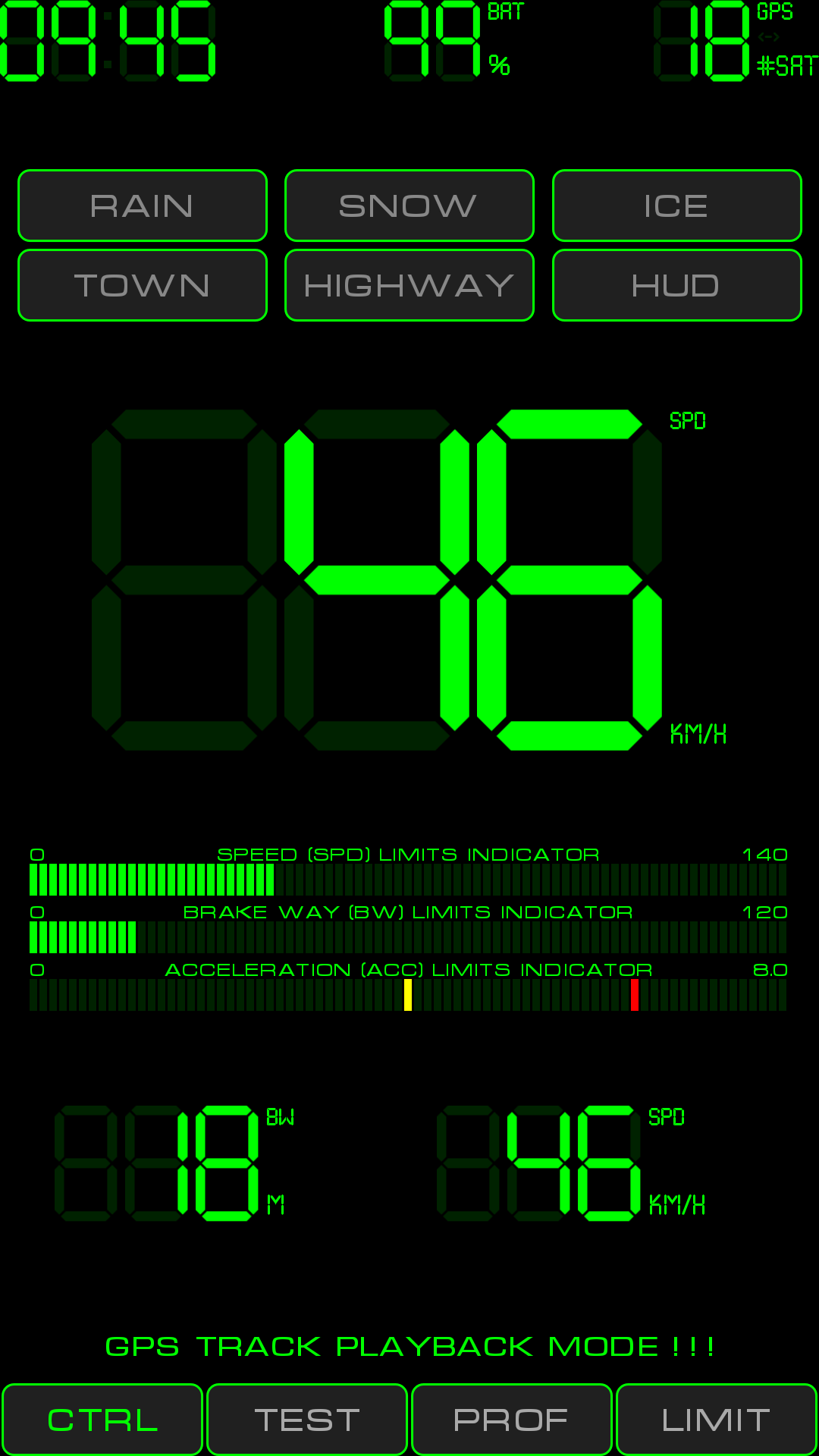
The interface consists from number of screens. Most important and often used are "CTRL", "TEST", "PROF", "LIMIT". User can switch between these screens using buttons at the bottom of the screen (on the left of the screen in portrait mode).
Each screen has its own purpose:
"CTRL" — (abbreviation from CONTROL) shows LCD indicators of selected parameters and limits indicators.
"TEST" — allows to perform deceleration tests and analyze its results. The test measures driver reaction time, brake system activation time and effective deceleration.
"PROF" — (abbreviation from PROFILE) profiles editor screen.
"LIMIT" — limits editor screen.
On every screen there are several common widgets: «digital clock», battery level meter and GPS satellites meter. GPS meter shows number of GPS\GLONASS satellites currently used for positioning and speed measurement. It also shows small arrow which lights up every time program receive new location from GPS. Tap on any of these three indicators will open main menu.
Main menu consists of:
About — shows information about version, copyright and usage terms.
Help — shows this manual.
GPS playback — allows to play previously recorded GPS track. It could be the file created by free GPSLogger software in cvs format with 1 sec recording intervals. Or it is possible to play embedded track. This function allows to setup PROFILES and LIMITS (and thus reaction of the program to various road conditions) in comfortable place and not while driving.
Global settings — screen to see and change application-wide settings..
Send logs to developer — it archives the log files and allows to send it to the developer via any e-mail client program installed on your phone. If you experience wrong or strange program behavior please use this function and type in exact description of the erroneous situation you’ve faced with.
Exit from app – allows to shut down the application.

Controls:
Switch buttons «RAIN», «SNOW», «ICE» - set current weather conditions. Only one button could be turned on at given moment in time. The button which turned on has colored text in it, the one which turned off has gray text. If all these buttons are turned off then program knows that there are normal dry conditions. Weather conditions affect on:
decisions which LIMITS to apply;
taking appropriate deceleration value from PROFILE for brake way, brake time and traction loss limits calculations.
Switch buttons «TOWN», «HIGHWAY» - sets the type of territory you are currently driving through. These buttons affects on decisions which LIMITS to apply.
«HUD» switch button (HEAD-UP DISPLAY) — turns mirroring of the display. When HUD mode is on you can project phone display on to windshield and see normal display picture in reflection from windshield.
Central LCD indicator — shows one of the selected parameters (tap on indicator to select needed parameter):
Current speed (SPD) — short abbreviation of parameter name is written on the upper left conner of each LCD indicator. Measurements units is written on the bottom left corner. This particular indicator show current speed as measured by GPS.
Brake way (BW) — this is calculated parameter. It represents the distance which is needed to completely stop the vehicle from current speed. This parameter takes in to account driver’s reaction time, brake system activation time and deceleration for current weather conditions (all from PROFILE). It has quadratic dependence from speed. For adequate calculation it is required to have reasonable values of river’s reaction time, brake system activation time and deceleration for various weather conditions in the PROFILE. These values could be measured using “TEST” screen.
Brake time (BT) - this is calculated parameter. It represents the time which is needed to completely stop the vehicle from current speed. This parameter takes in to account driver’s reaction time, brake system activation time and deceleration for current weather conditions (all from PROFILE).
Acceleration (ACC) — ACC indicator shows projection of total acceleration vector on to horizontal plane (because usually we are not interested in gravitation and car jumps on road irregularities). Another way to look at its value – use it as traction meter (i.e. to see how much of traction force already “spent”). As “acceleration” (a) is closely related to the “force” (F) ( F = m*a ) we’ll further use these two terms interchangeably.
The maximum deceleration which your car could achieve (and thus the maximum traction force) is written in the PROFILE for various weather conditions (either measured by TEST screen or obtained in other way). This is also maximum acceleration you car is able too deliver because it is (this is true for most usual civil cars) limitation arising from maximum achievable traction force between tires and road. If acceleration (thus force) applied to the car will be more than deceleration values from PROFILE then traction will be lost and such car will slide over the road. For example, if maximum deceleration for current weather conditions is 5 m/s2 and ACC indicator shows 2.5 m/s2 when driving under same weather conditions – it means that half of traction abilities are already in use. Traction ability is “consumed” when you accelerating (pushing throttle pedal), when you braking (either by brake pedal or by engine), when you drive on curved trajectory (centripetal acceleration and its centrifugal force). Therefore when the sum of all accelerations will be equal or slightly more than measured maximum deceleration of the car then such car will loss traction. When driving on curved trajectories loss of traction will occur even earlier (when ACC will show, say 50% of maximum deceleration – particular value depends on vehicle, tires and road) because tires will work worse under sideway loads.
The application is distributed with two per-configured LIMITS for acceleration. The first one has limit value of 50% (counted from deceleration written in the PROFILE for given weather conditions). It serves as traction loss indicator during turns. Second one has value 80% and serves as traction loss indicator on straight road parts. You can adjust the values of these LIMITS according to the specific behavior of your vehicle.
ACC indicator present on two screens (CTRL and TEST) and in several places on CTRL screen. But only central LCD indicator of CTRL screen gives access to very important function — lock (or fixation) of the horizontal plane versus phone’s body. After the phone is placed in to the holder (inside the car) it is desirable to tell the program that it could “remember” current position of world horizontal plane relative to phone’s body. Let’s call this operation “horizon fix”. During the horizon fix the car should be stationary and should be in relatively horizontal position (not on rising or descending part of the road). To do horizon fix you need to tap central indicator and choose last menu item «Fix horizon». ”FIX” sign will light up on the right of ACC indicator. After horizon in fixed don’t move the phone relative to the car. If you move it relative to the car then its values will not be reliable anymore and you should fix horizon again by switching to automatic continuous horizon detection using “Auto adjust horizon” menu item and then do horizon fix procedure again.
If horizon is not fixed then program will work in automatic horizon detection mode and will fix horizon from time to time when it decides that its appropriate. By default program will start in this automatic mode. In general “FIX” mode is better and more informative when car is climbing on a hill or descending from it. Here is the difference...
In «FIX» mode, when you climb or descend, you’ll see that ACC shows non zero values (it could be significant numbers e.g. 1-3 m/s2 — depends on road inclination) even if you feel you are not accelerating or braking. This is part of gravitation which pulls you towards center of the Earth. On climbs and descends gravitation also “consumes” part of the traction abilities of your car. For example, if maximum deceleration of your car is 6 and car descends from a hill and ACC shows 2 then you have just 4 m/s2 of traction for braking and other maneuvers.
In automatic horizon detection mode on climbs and descends gravitation will not be taken in to account so if you are not accelerating or braking ACC will show values close to 0.
TNT-meter (TNT) — represents energy release in hypothetic situation when car (on current speed) hits in to massive stationary object. It has quadratic dependence from speed. For correct readings it is important to enter actual vehicle weight in the PROFILE.
Speed limits indicator — shows limits set for speed and also shows violations of the limits. Set limits are visible as colored bars. Color from appropriate LIMIT is used to draw this bar and also to signal about limit violation. Beginning of indicator’s scale corresponds to 0 speed. Maximum value is defined in the PROFILE’s «Maximum speed» field. This should be the maximum speed you intended to drive with (and not the theoretical maximum speed of your car).
Brake way limits indicator — same as above but for brake way.
Acceleration limits indicator — same as above but for acceleration.
Bottom left LCD indicator - shows one of the selected parameters (tap on indicator to select needed parameter):
Current speed — same as on central LCD;
Brake way — same as on central LCD;
Average speed — average speed during program run. After program restart average speed will be reset to 0. Its possible to manually zero it by taping on indicator and choosing “Reset average speed” menu item;
Maximum speed - maximum speed during program run. After program restart maximum speed will be reset to 0. Its possible to manually zero it by taping on indicator and choosing “Reset maximum speed” menu item;
TNT-meter — same as on central LCD.
Bottom right LCD indicator - shows one of the selected parameters (tap on indicator to select needed parameter):
Current speed — same as on central LCD;
Acceleration — same as on central LCD;
Brake time — same as on central LCD;
TRIP A — trip distance from start of the program. After program restart maximum speed will be reset to 0. Its possible to manually zero it by taping on indicator and choosing “Reset TRIP A” menu item;
TRIP B – trip distance covered with particular PROFILE. This value is stored in to the PROFILE and after program restart TRIP B counting will begin from last stored value. This counter shows which distance is covered on using given PROFILE. Its possible to manually zero it by taping on indicator and choosing “Reset TRIP B” menu item;
TRIP C - trip distance covered with any PROFILE. The value is stored program wide and after program restart TRIP C counting will begin from last stored value. This counter shows which distance is covered with “Safe Speed” running. Its possible to manually zero it by taping on indicator and choosing “Reset TRIP C” menu item.
Informer string — one line text widget below bottom LCD indicators. It present on all program screens and shows information about current status, errors or successfully done operations.
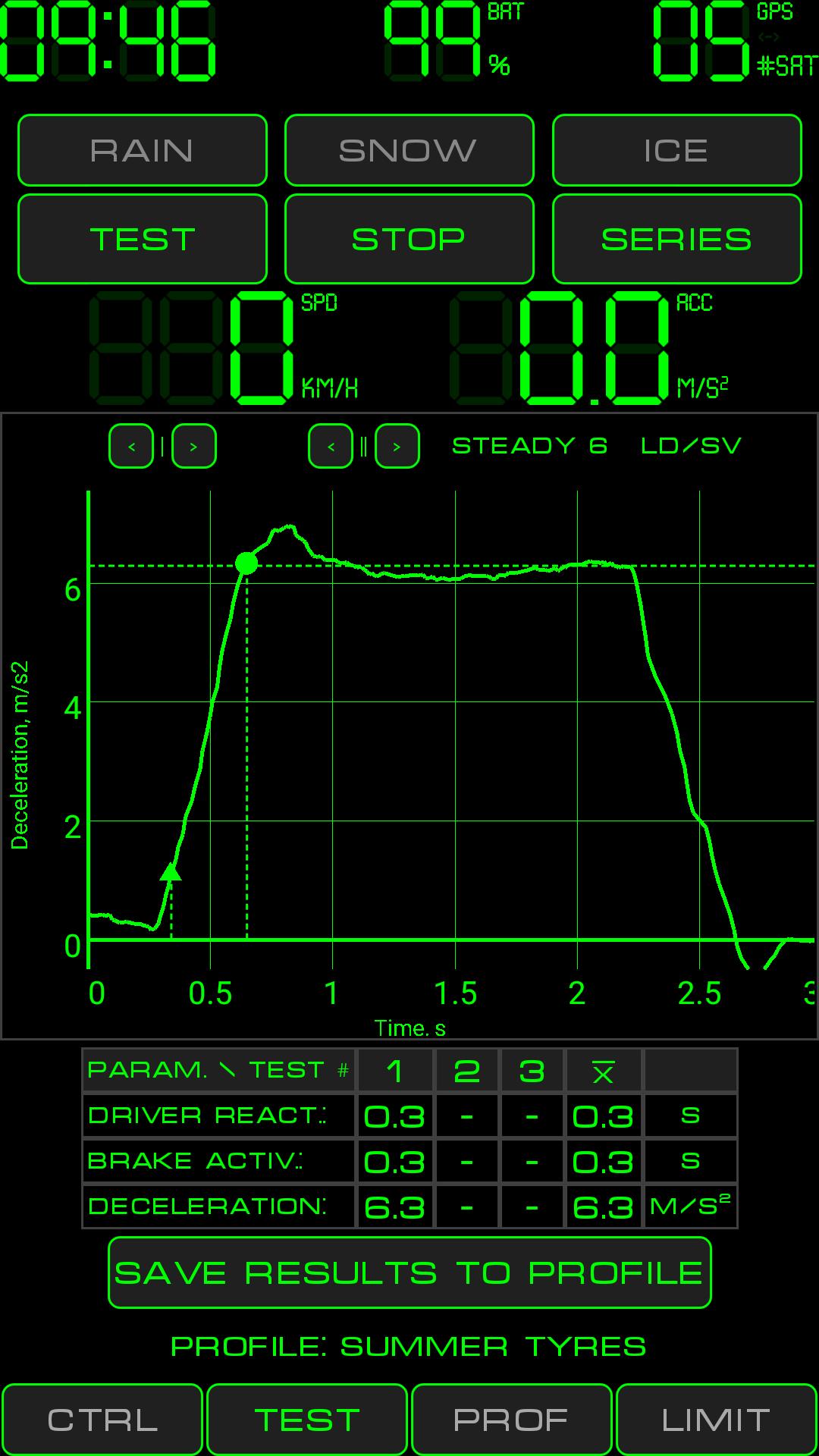
“TEST” screen allows to test braking abilities of your vehicle. Using this screen you can collect objective data which is essential for calculation of brake way, brake time and traction loss limits. Test results are stored in the PROFILE.
You can do one single test or series of three tests. Of course its better to do the series as it will deliver more reliable results.
For testing you need to choose free (from other vehicles) road without climbs and descends. Please make sure that your test will not create dangerous situation on the road for you and for others!
Single test (as well as each test in series) consist from next steps:
Mount your phone inside the car so that its bottom cover is pointed forward – in the car moving direction. The screen must be in vertical plain and also perpendicular to the car’s longitudinal axis. Mount the phone as firmly as you can.
Then it is very desirable to calibrate “no motion” sensor implemented in the program. Such calibration needs to be done once for every vehicle where “Safe Speed” is used. To do that:
Stop your car but keep engine running;
Check for color of “STEADY” sign above the graph on TEST screen. The sign should be colored with the same color as whole user interface (green by default). If it is gray – this means that “no motion” sensor “think” that your car is in motion (probably due to engine vibrations);
If “STEADY” sign is gray then tap it once and in the opened menu choose «- sensitivity». Decrease sensitivity till you’ll see stable colored light of “STEADY” sign;
Then start driving - “STEADY” sign should go gray and should stay gray while you are driving;
If “STEADY” sign is colored when vehicle is stopped and also colored when it is moving – this means that sensitivity of “no motion” sensor is too low. Tap “STEADY” sign and in the opened menu choose «+ sensitivity». Change the sensitivity until you’ll see stable colored light of “STEADY” sign when car is not moving and stable gray light when it is moving.
Choose current weather conditions with «RAIN», «SNOW» or «ICE» buttons. If there are normal conditions leave all buttons inactive (gray).
Push «SERIES» or «TEST» button while your car is parked.
Program starts telling you that you need to increase the speed.
Upon 30 km/h or 20 miles/h program will tell you that you need to brake after signal.
There will be short «beep» signal.
Start braking immediately you hear «beep».
Continue to brake until full stop of the vehicle.
Program will show the graph (dependency of deceleration from time) and also will show measured values for driver reaction time, brake activation time and effective deceleration.
If you see that program determined time parameters incorrectly then you can use «<» and «>» buttons above the graph to make corrections.
Press «Save results to profile» («SAVE» in portrait screen orientation) to write measured values (mean driver reaction time, brake activation time and effective deceleration) in to current PROFILE. Deceleration will be written to the PROFILE field which corresponds to chosen weather conditions.
Also you can save raw test data in to a file for future analysis. Tap “LD/SV” text above the graph and choose “Save” from opened menu. Resulting file will have name with date, time and word “raw” in its name. Later on you can load saved test data and see it again on the graph. This is useful for analysis of your braking technique and how it is progresses with the time.
Lets look at typical deceleration test graph to better understand all underlying processes. The graph below was taken during the deceleration test on road covered by snow.

The part of the graph between 0 (X axis is in seconds) till point A corresponds to the driver reaction time. Beginning of X axis on the graph corresponds to the start of «beep» signal. We see that after “beep” deceleration doesn’t increase because driver needs some time to understand whats happening, to move the leg from accelerator pedal to brake pedal and to actually start pressing the brake. In this particular test this time is 0.7 seconds.
The part of the graph between A and B corresponds to the brake system activation time. During this time deceleration grows from 0 to the near maximum value. This time is needed to completely push down brake pedal (thus creating nominal pressure in the hydraulic brake system) and for reaction of car suspension system and tires. In this test brake system was activated in 0.3 seconds which is pretty standard value for passenger cars.
The part of the graph between B and C corresponds to active braking stage. As we can see there is some room for brake skill improvement of this particular driver – at the end of 2nd second there is fall in deceleration to 2 m/s^2.
The part of the graph between C and D corresponds to practically stopped car.
Big round points near A and B (and also dotted lines) automatically put there by the program. These points represent beginning and end of the brake process stages described earlier. If program determines places of these points incorrectly then driver reaction time as well as brake system activation time will be incorrect. You can manually adjust positions of the points using «<» and «>» buttons above the graph. Left pair of buttons moves point A, right pair — point B.
Dotted line which is parallel to X axis on 2.8 m/s^2 height represents automatically determined effective deceleration.
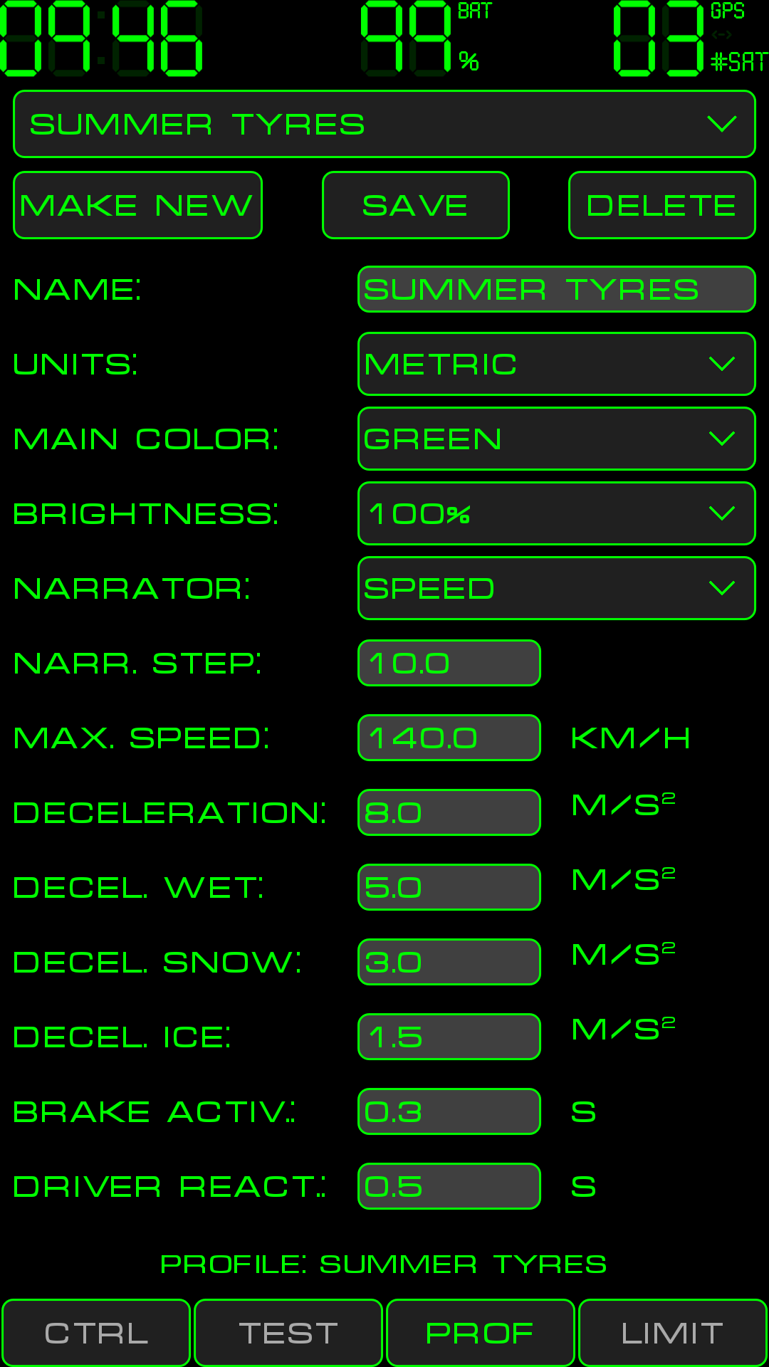
PROFILE is easily changeable container with various program settings. Most important settings are those which defines car braking abilities. It is recommended to create new PROFILE (or choose appropriate existing one) when braking parameters differs from current PROFILE. This could be situations such as:
using the program on one phone but with several different vehicles which have different braking abilities (e.g. personal car and working car).
tires change from summer type to winter type.
using the program with one phone (or car embedded device) on one car but by differed drivers with different driver’s reaction time.
Each PROFILE must contain deceleration values (for various weather conditions), driver reaction time and brake system activation time. These parameters could be measured using “TEST” screen.
Controls (from top to bottom):
CURRENT PROFILE SELECTOR — choosing the PROFILE with top selector triggers two things:
Chosen profile becomes the “current” one and apply immediately for all screens.
All fields of chosen PROFILE are loaded in to “PROF” screen and could be edited.
MAKE NEW – creates new PROFILE with default values. Press this button each time you need new PROFILE.
SAVE — saves edited data in to permanent storage. Don’t forget to press this button after editing the PROFILE.
DELETE — removes chosen PROFILE.
NAME — meaningful (for you) PROFILE name. This name appears in the “CURRENT PROFILE SELECTOR” and also in the Informer (bottom information test line).
UNITS — metric or imperial.
MAIN COLOR — allows to choose one of 7 colors for the user interface.
BRIGHTNESS — defines the screen brightness for the PROFILE.
NARRATOR — allows to switch pronunciation of current value for either speed or brake way.
NARRATOR STEP — defined minimum change of narrated parameter (speed or brake way) between two consecutive narrations.
MAXIMUM SPEED — put there maximum speed you intended to drive with. This value is used to scale SPEED LIMITS INDICATOR and BRAKE WAY LIMITS INDICATOR on “CTRL” screen.
DECELERATION — this is deceleration you vehicle is able to achieve when braking on normal dry road.
DECELERATION WET — deceleration on wet road.
DECELERATION SNOW — deceleration on road covered by snow.
DECELERATION ICE — deceleration on road covered by ice.
DRIVER REACTION — driver reaction time. This is the time between the thought “I need to brake” till touch of the driver’s foot with brake pedal. The time is spend for nerve impulse travel through driver’s body and for relocation of foot from throttle to brake pedal.
BRAKE ACTIVATION — this is time needed to activate vehicle’s braking system. For many modern passenger cars this parameter is about 0.3 sec. After the driver start pushing brake pedal some time is need to create working pressure in hydraulic brake system and also for slight deformation of suspension system and tires..
VEHICLE WEIGHT — used for TNT-meter on «CTRL» screen.
LIMITS — these are 10 selectors to attach LIMITS to this particular PROFILE. Position of LIMIT in this list defines LIMIT’s priority. First LIMIT has maximum priority, 10th – has minimum priority. Priorities are use when several LIMITS for the same PARAMETER (e.g. speed) are violated at the same time. In this case only one LIMIT with highest priority will be signaled as violated (by color flashes and\or by sound). Example… Assume we have two LIMITS for speed. Limit1 has VALUE equal 60, Limit2 has 80. Both LIMITS has rule «GREATER» (i.e. continuous signalization when current speed is greater then LIMIT’s value). We want to see Limit1 signalization that until current speed of 80 and we’d like to turn off Limit1 signalization after reaching speed 80 but turn on signalization of Limit2. To have such behavior we should put Limit2 higher in the list..
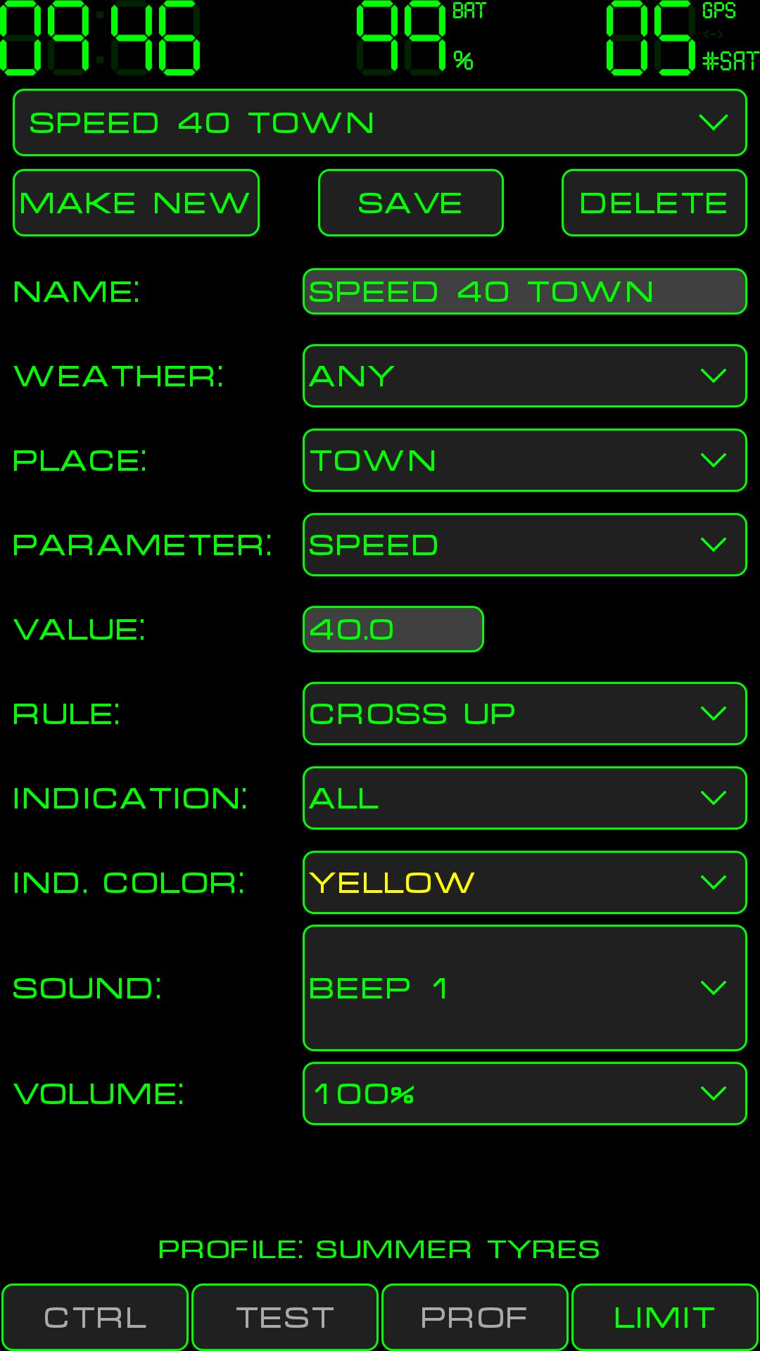
LIMIT is a setup object of “Safe Speed” which defined when and how program will react on changing driving parameters. One LIMIT could be used in many PROFILEs.
Controls (from top to bottom):
LIMIT SELECTOR — allows to choose LIMIT for view and edit. Upon choose of the LIMIT all its fields will be loaded in to “LIMIT” screen and could be edited.
MAKE NEW – creates new LIMIT with default values. Press this button each time you need new LIMIT.
SAVE — saves edited data in to permanent storage. Don’t forget to press this button after editing the LIMIT.
DELETE — removes chosen LIMIT.
NAME — meaningful (for you) LIMIT name. This name is shown in “LIMIT SELECTOR” on top of “LIMIT” screen as well as in limits section of “PROF” screen. It is proposed to follow simple naming convention: «limiting parameter» «limit value» «place» «weather conditions». For example, the name «SPEED 40 TOWN SNOW» gives enough information when you’ll be attaching LIMITS to PROFILE on “PROF” screen.
WEATHER — defines weather conditions when this LIMIT should be evaluated. Possible options: Any, Normal, Wet, Snow, Ice. The LIMIT will be shown on limits indicator (on “CTRL” screen) and will have chance to signal its violation only when its WEATHER field match with weather conditions selected by “weather” buttons on “CTRL” screen.
PLACE — defines the area where LIMIT should be evaluated. Options: Any, Town, Highway. This parameter separates two very different situations: driving in inhabited locality versus driving on highway. The LIMIT will be applied only when its “PLACE” field match “TOWN”/”HIGHWAY” buttons on “CTRL” screen.
PARAMETER — defined the parameter which this LIMIT will control. Options: Speed, Brake way, Acceleration.
VALUE — this is limit value to trigger the LIMIT. Measuring units of this value is defined in PROFILE to which this limit is attached.
VALUE % — for acceleration its limit value is defined as % from weather specific deceleration stored in PROFILE. For example if “RAIN” button pressed on “CTRL” screen then LIMIT for acceleration with “VALUE %” = 50 will have actual limit value as 50% of “DECELERATION WET” from the PROFILE this LIMIT is attached to.
RULE — defines the logic of the LIMIT:
CROSS UP — the LIMIT will be violated (and signaled) when actual (measured/calculated) value of the controlled PARAMETER become equal or greater then VALUE in the LIMIT. Signalization of LIMIT violation will be short and one off (1 sec of visual signalization and sound will be played once);
CROSS DOWN – similar to above rule but for situation when actual value goes below limit’s VALUE;
GREATER — the LIMIT will be violated (and signaled) when actual (measured/calculated) value of the controlled PARAMETER become equal or greater then VALUE in the LIMIT. Signalization of LIMIT violation will continue till actual value is greater than LIMIT’s VALUE. The difference from “CROSS UP” rule is that “GREATER” rule will give continuous signalization while “CROSS UP” will give one-off signalization;
LESS — similar to above rule but for situation when actual value goes below limit’s VALUE.
INDICATION — define the way program will signal about LIMIT violation. Options: All, Visual, Sound.
INDICATION COLOR — defines the color of limits violation indicator upon LIMIT violation event (in case of visual indication).
INDICATION SOUND — defines the sound to be played upon LIMIT violation event (in case of sound indication). All embedded sounds are divided in to several groups (Avia, Beep, Birds, Robots, Submarine, Wooo). The last item in sound selector is “BY VOICE”. It turns on violation signalization by narrator voice.
VOLUME – sets the volume of INDICATION SOUND.
“Global settings” screen could be opened from main program menu. Main program menu will appear after single tap on “digital clock” widget.
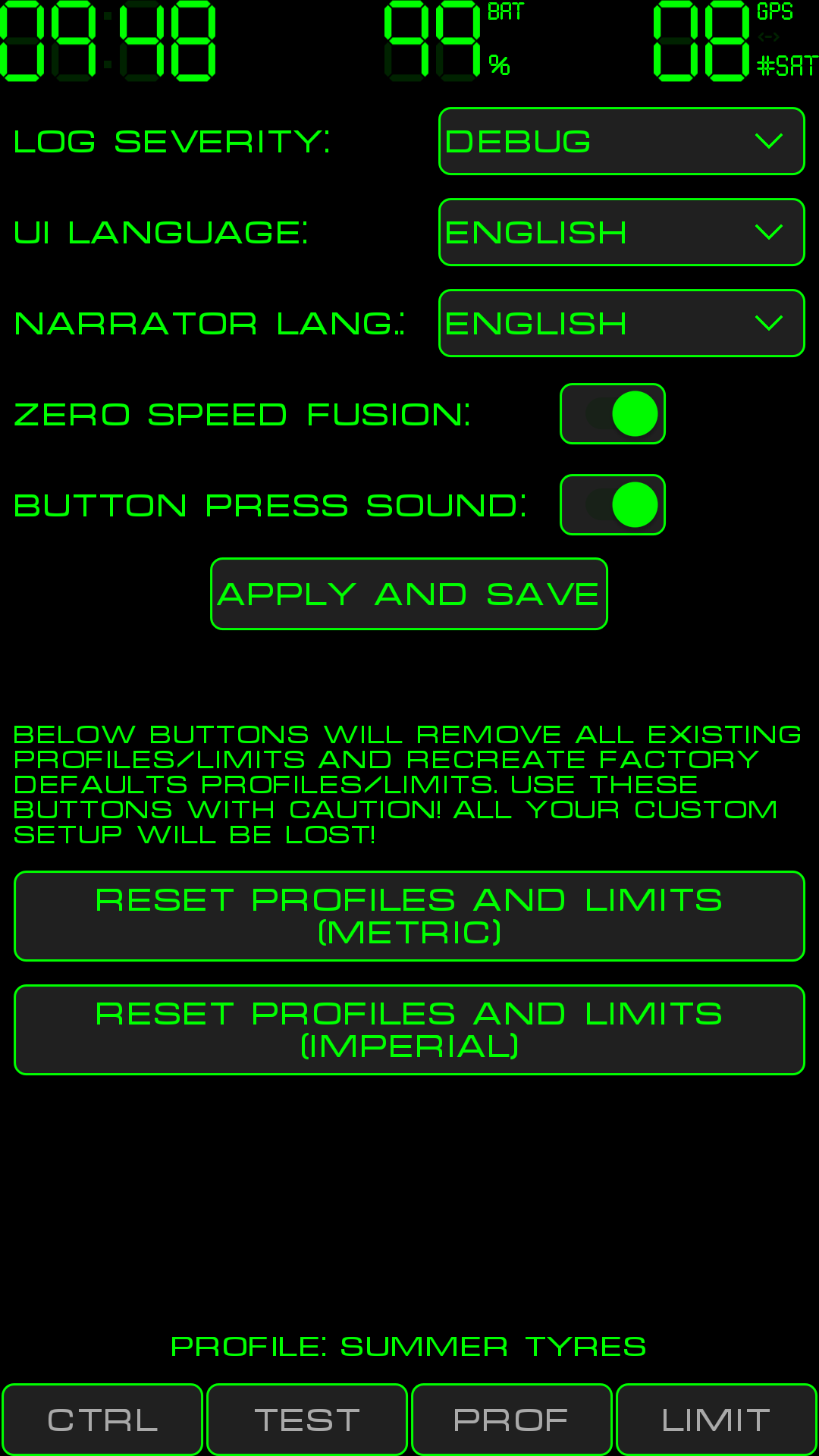
Controls (from top to bottom):
LOG SEVERITY - controls amount of information in log files.
UI LANGUAGE - forces switch of User Interface language. If settings was never set and saved then “Safe Speed” will have UI language according to locale of your phone. After saving this setting phone locale will be ignored.
NARRATOR LANGUAGE – forces switch of narrator language. If settings was never set and saved then “Safe Speed” will have narrator language according to locale of your phone. After saving this setting phone locale will be ignored.
ZERO SPEED FUSION — turns on/off correction on GPS speed using other phone sensors. If other sensors shows that phone is not moving then GPS speed is ignored and assumed to be 0. This mode helps to keep more precise average speed and trip distance values.
BUTTON PRESS SOUND - toggle button press sound..
APPLY AND SAVE - saves all settings and put them in effect.
RESET PROFILES AND LIMITS — these buttons removes all existing PROFILEs and LIMITS and creates factory default one.
“Accelerometer calibration” screen could be opened from main program menu. Main program menu will appear after single tap on “digital clock” widget.
Embedded accelerometer (phone sensor which measures acceleration) may deliver low accuracy readings due to bad factory calibration, aging and other reasons. To take more precise acceleration readings “Safe Speed” implements in-program accelerometer calibration function.
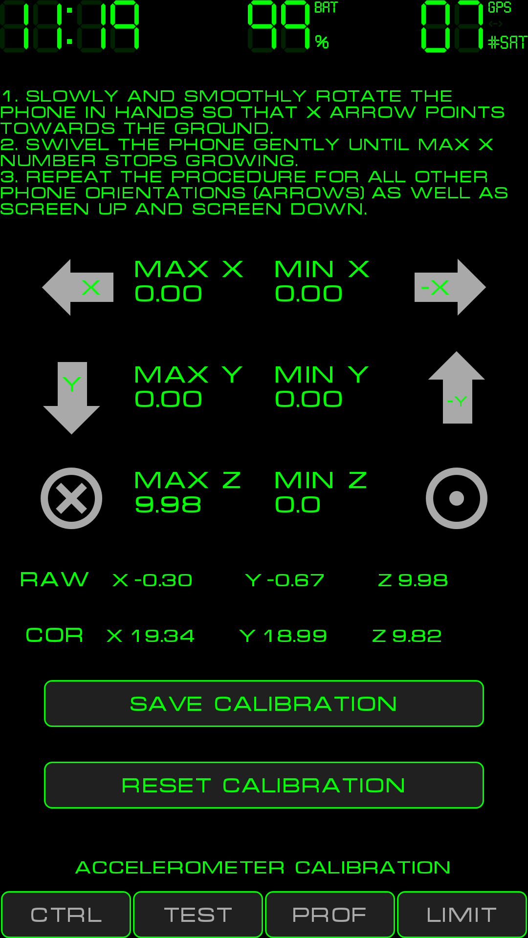
Calibration procedure:
Open “Accelerometer calibration” screen.
Hold the phone aweigh with your hands. Gently and smoothly turn the phone so that Х arrow is pointed vertically to the ground.
Slowly swivel the phone near obtained (on step 2) position to get maximum «MAX X» reading.
Repeat steps 2-3 for all directions marked by arrows as well as screen up and screen down phone positions.
As a result all MIN and MAX fields should have values (typically) in range from 9 to 11 (-9 to -11). Ideally factory calibrated accelerometer will show 9.82 (free fall acceleration) for all these readings but in real world it is not so.
If some of the MIN/MAХ values are too big (by module) i.e. greater than 11 — probably its because you’ve excessively shaken the phone during the calibration. Hand movements during the calibration must be really smooth. If some value appears to be strange (bigger than 10.5 - 11) zero it by tapping it once and recalibrate given axis.
Save calibration results by pressing “SAVE CALIBRATION”. Other applications on your phone will not know about this calibration and will continue to work as before. Only “Safe Speed” will deliver more precise acceleration reading after calibration.
If wrong calibration was saved and you don’t want to do calibration again then you can press “RESET CALIBRATION” button. After that “Safe Speed” will use no corrections for accelerometer data pretending that calibration procedure was never done before.
“RAW” string shows current raw reading from accelerometer. “COR” string shows corrected values. If calibration done properly then “COR” values are in range -9.82 to +9.82 in any phone orientation.
To further check calibration results (after «SAVE CALIBRATION» pressed):
Go to “CTRL” screen
Tap central indicator and choose “Show Acceleration”
Tap central indicator and choose “Fix Horizon”
Now rotate the phone in 3D space – the maximum acceleration you’ll see should be 9.8 м/с2 (free fall acceleration).