Topic: VibrAn - vibration analysis application
VibrAn - users manual
1. Limitation of liability
THE SOFTWARE IS PROVIDED “AS IS”, WITHOUT WARRANTY OF ANY KIND, EXPRESS OR IMPLIED, INCLUDING BUT NOT LIMITED TO THE WARRANTIES OF MERCHANTABILITY, FITNESS FOR A PARTICULAR PURPOSE AND NON INFRINGEMENT. IN NO EVENT SHALL THE AUTHOR BE LIABLE FOR ANY CLAIM, DAMAGES OR OTHER LIABILITY, WHETHER IN AN ACTION OF CONTRACT, TORT OR OTHERWISE, ARISING FROM, OUT OF OR IN CONNECTION WITH THE SOFTWARE OR THE USE OR OTHER DEALINGS IN THE SOFTWARE.
2. The purpose
VibrAn is designed for estimation of machines (mainly) vibration levels.
The program works with accelerometer sensor embedded in your phone. It gets the raw data from the sensor, process it and shows visually the result.
Vibrations from machine (under estimation) needs to be transferred to the phone's body. It could be done by placing the phone over the machine. If machine vibrates too intensive then it is better to dump such vibrations prior transferring it to the phone's body. For dumping excessive vibrations one could use spacer between the machine and phone made from thick cloth or insulation foam.
VibrAn presents resulting information in two domains:
* Time domain
* Frequency domain
In time domain it shows acceleration amplitude (its components or vector length) on a timeline. In frequency domain it shows acceleration amplitude at given frequency.
Looking at data in frequency domain only make sense if the processes we try to investigate are of periodic nature (e.g. constantly rotating shaft).
There are two ways to estimate vibrations:
* Absolute estimation: if standard vibrations levels for that particular machine part is known then using "CAPT" (Capture) screen it is possible to compare actual vibration (use time domain - "ACCELERATION" mode) with standard one.
* Relative estimation: if standard vibrations levels are not known but it is required to lower vibrations of machine part to some "acceptable" level then using "CAPT" screen we need to record the file with accelerometer data before manipulations/repair of the machine part. Then after manipulations/repair another file is recorded. Both files are loaded via "ANLZ" (Analyze) screen and compared there in time or frequency domains.
3. User interface
Switch between screens with buttons at the bottom "CAPT", "ANLZ", "SET", "HELP".
Main functions of each screen:
* "CAPT" - shows acceleration in near real-time mode (both as time sequence or as a spectrum), records accelerometer data in to file.
* "ANLZ" - loads files with accelerometer data, process and visualize the data.
* "SET" - general program settings
* "HELP" - usage information
4. "CAPT" screen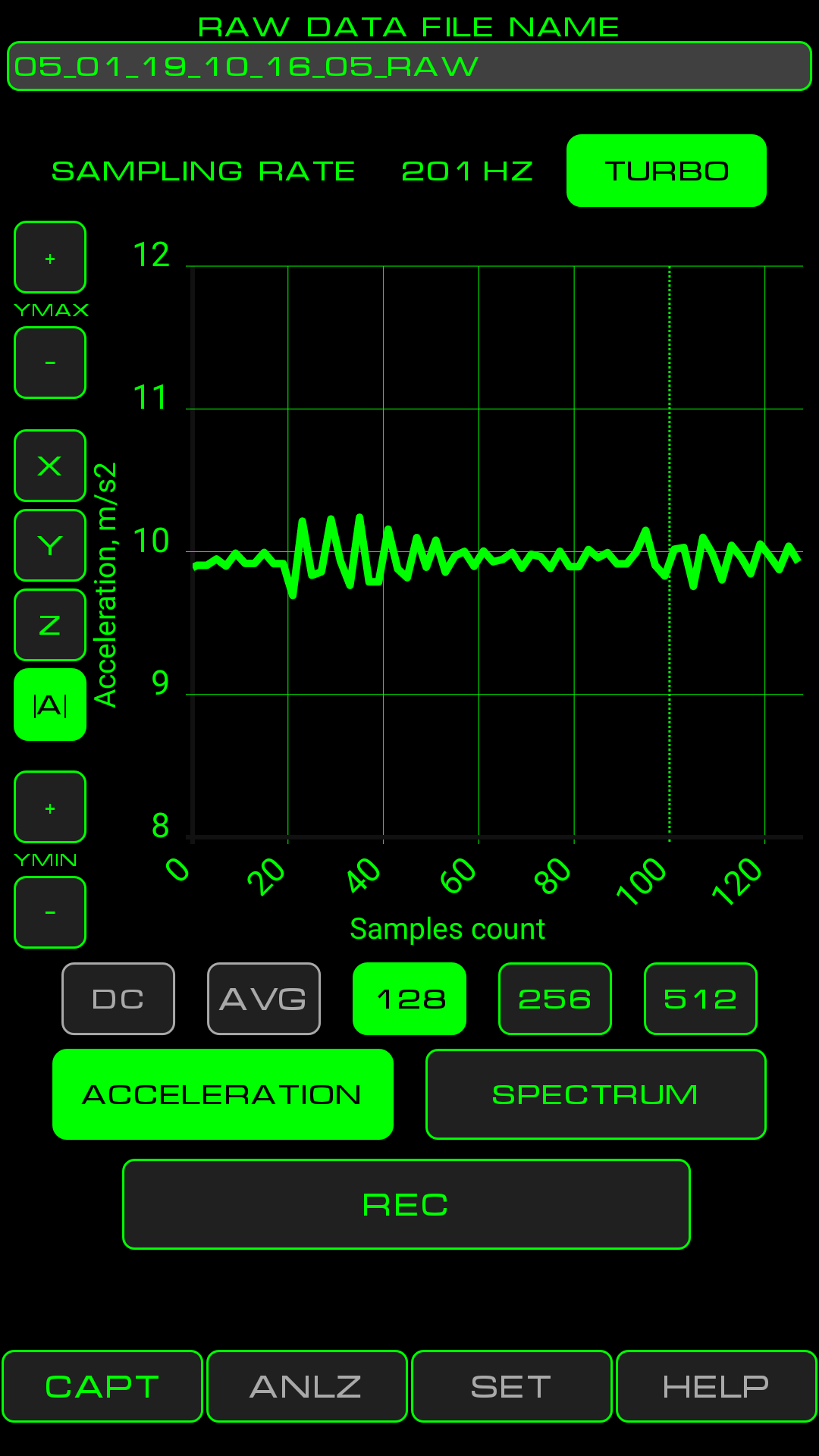
Controls:
- RAW DATA FILE NAME - accelerometer data will be saved in to the file specified in that field. You can type in the file name manually or use automatically generated file names. These files are stored under SDCARD/Vibran
- SAMPLING RATE - shows rate of incoming data from accelerometer.
- TURBO - allows to double sampling rate. Most phones delivers just 100Hz sampling rate in normal mode. In most cases its not enough as a spectrum of such signal will span from 0Hz to just 50Hz. Many machine parts has periodicity of movement at 50 - 60 Hz and even more. Therefore it is viable to have sampling rate of 200 Hz and more and thus have the ability to see spectrum of 0 - 100 Hz.
- YMAX and YMIN - and their buttons "+" and "-" allow to change the scale of Y axis.
- X, Y, Z - switch plotting between individual acceleration components associated with particular space axis.
- |A| - toggle plot to show length of acceleration vector (i.e. vector sum of X, Y, Z )
- ACCELERATION - toggle time domain plot representation. Acceleration will be shown as time sequence.
- SPECTRUM - toggle frequency domain plot representation. Acceleration will be shown as function of frequency.
- DC - toggle display of DC signal component at 0 Hz bin. The button works only when "SPECTRUM" mode is on.
- AVG - toggle averaging of 10 sequential spectrum data sets. Improves signal/noise ratio by factor of 3 but delays the signal. The button works only when "SPECTRUM" mode is on.
- 128, 256, 512 - in "ACCELERATION" mode these buttons define width of time window shown on plot. In "SPECTRUM" mode these buttons define spectrum resolution (128 gives wider spectrum lines - less resolution; 512 gives higher resolution).
- REC - toggle recording of accelerometer data in to file. Raw accelerometer data is written to the file. Buttons on this screen (except for TURBO) doesn't take any effect on written data. Recording length (time) is limited only by free space on SD card, but "ANLZ" screen can load just 10000 samples from one file. After press of REC button there will be recording time displayed on it. When there will be 8000 samples written to the file the text on REC button will become yellow. When there will be 10000 samples written to the file the text on REC button will become red, but recording will continue.
5. "ANLZ" screen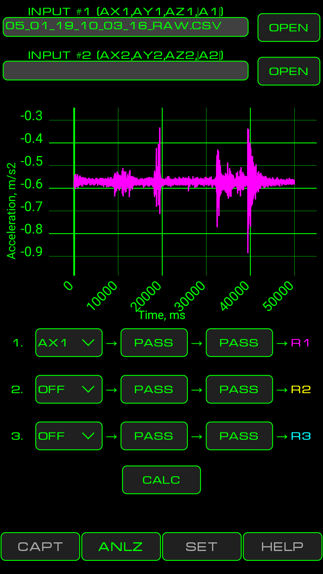
Controls:
- INPUT #1 and button OPEN - the button opens file opening dialog. INPUT filed will contain name of the loaded file. This file will be the source of named data arrays. AX1 - arrays of Х acceleration component, AY1 - ... Y component, AZ1 - ... Z component, |А1| - array of acceleration vector lengths.
- INPUT #2 and button OPEN - same as previous point but for second input file.
- CALCULATION CHAIN 1 - begins with number 1 and ends with R1 (result 1) symbol. First control element ("input selector") in calculation chain (shows АХ1 value on above screenshot) defines the input for this chain. Then two operators follows (PASS and PASS on the above screenshot).
- Input selector - first control in each calculation chain. Possible values are any of loaded data arrays АХ1 - |A1| and АХ2 - |А2|. For chain #2 is is also possible to select R1 (calculation result of chain #1) as input. For chain #3 is is also possible to select R1 or R2 as input. If selector is set to "OFF" then this chain will not be calculated.
- Operators - when any of operators controls are pressed there will be operator settings dialog window shown. Available operators:
PASS - pass signal through without any modifications;
BPF - Band Pass Filter. It can be set to work in any of 20 frequency bands with 5 Hz width each. These 20 bands covers 1- 100 Hz range. Input and output of BPF is time domain data;
FT - Fourier transform. Switches data domain from time to frequency. The output will be the spectrum of input signal;
RFT - reverse Fourier transform. Switched data from frequency domain in to time domain;
- R1 - R3 - calculation results which by default are shown on plot. Presence of particular result on plot can be switched on/off by touching R1 - R3 symbols.
- CALC - initiates calculation and plot process.
6. "SET" screen
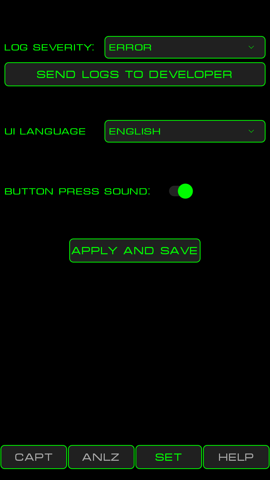
Controls:
- Log severity - controls amount of information in log files.
- SEND LOGS TO DEVELOPER - constructs e-mail with attached log files and passes this e-mail to the default email client program for sending. Use this button when you want to report strange or erroneous program behaviour.
- UI LANGUAGE - forces switch of UI language. If settings was never set and saved then VibrAn will have UI language according to locale of your phone. After saving this setting phone locale will be ignored.
- BUTTON PRESS SOUND - toggle button press sound.
- APPLY AND SAVE - saves all settings and put them in effect.